|
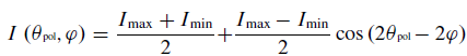
Home Publications York Polarisation Photometric stereo Q-Bot Composites Theory 1 Theory 2 Theory 3 Theory 4 Polarisation ImagingFor the cases where the incident light is unpolarised, the simplest and most common method of measuring polarisation is to take a sequence of images with a rotating linear polariser. Consider a camera's field of view where the incoming light is partially linearly polarised with varying degrees between 0 and 100%. The aim is to acquire a polarisation image: a three channel image where each pixel has components corresponding to (1) the greyscale intensity, (2) the degree of polarisation and (3) the phase angle of the linearly polarised component of the incoming light. As the polariser on the lens rotates, the transmitted intensity at each point is given by the transmitted radiance sinusoid:
where θpol is the polariser orientation, Imin and Imax are the minimum and maximum observed pixel brightnesses and φ is the phase angle. The transmitted radiance sinusoid is shown graphically below.
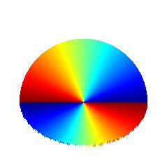
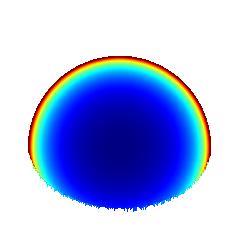
The complete polarisation image is then constructed by fitting the transmitted radiance sinusoid to three or more different intensity images for different polariser angles. This assumes that the pixel brightness is proportional to the light impinging on the sensor, i.e. the camera response function is linear. For typical imaging equipment, the intensity component is in the range [0,255], the degree of polarisation is always in the range [0,1] and the phase is always in the range [0,180°). The figure below shows a synthetic example of the three components of a polarisation image for a diffusely reflecting hemisphere.
A major weakness of many polarisation methods is the amount of time needed to acquire the data (the actual processing of the data is often highly efficient). For the rotating polariser method described above, three or more images are required with the polariser at different orientations. This limits applications to static scenes. Matters were improved after the development of polarisation cameras whereby a full polarisation image can be captured in a single frame. There have been several methods devised for this with perhaps the most common being to mount a microscopic polarising filter above each element of the sensor, but at varying orientations. A current market leading product is the XCG-CP510 sensor developed by Sony. |